Diodes
A diode is a two-terminal electronic component that conducts current primarily in one direction, a behavior known as asymmetric conductance¹. It has low (ideally zero) resistance in one direction and high (ideally infinite) resistance in the other¹.
The most common type of diode in use today is the semiconductor diode, which is a crystalline piece of semiconductor material with a p–n junction connected to two electrical terminals¹. This type of diode has an exponential current–voltage characteristic¹.

Diodes were first discovered by German physicist Ferdinand Braun in 1874¹. Today, most diodes are made of silicon, but other semiconducting materials such as gallium arsenide and germanium are also used¹.
The primary function of a diode is to allow an electric current to pass in one direction (called the diode's forward direction), while blocking it in the opposite direction (the reverse direction). This unidirectional behavior is called rectification and is used to convert alternating current (AC) to direct current (DC)¹.
Diodes can be found in various applications such as rectifiers to convert AC power to DC, demodulation in radio receivers, and can even be used for logic or as temperature sensors¹. A common variant of a diode is a light-emitting diode, which is used as electric lighting and status indicators on electronic devices¹..
A diode can act as a rectifier, which is a device that converts alternating current (AC) into direct current (DC). This is possible because diodes allow current to flow in only one direction⁴.
The rectification process involves a diode circuit, where the diode is forward biased during the positive half of the AC cycle, allowing current to pass through. During the negative half of the AC cycle, the diode is reverse biased, blocking current flow². This results in an output voltage that is solely in the positive half of the cycle².
There are two primary methods of diode rectification:
1. **Half Wave Rectifier**: In a half-wave rectifier, only one half of each AC input cycle (the positive or negative half) is rectified². When the diode is forward biased, it offers low resistance and allows current to flow. In the opposite half cycle, when it's reverse biased, no current flows².

2. **Full Wave Rectifier**: A full-wave rectifier rectifies both the positive and negative halves of the AC input cycle². This results in a higher average output voltage and less ripple than a half-wave rectifier².
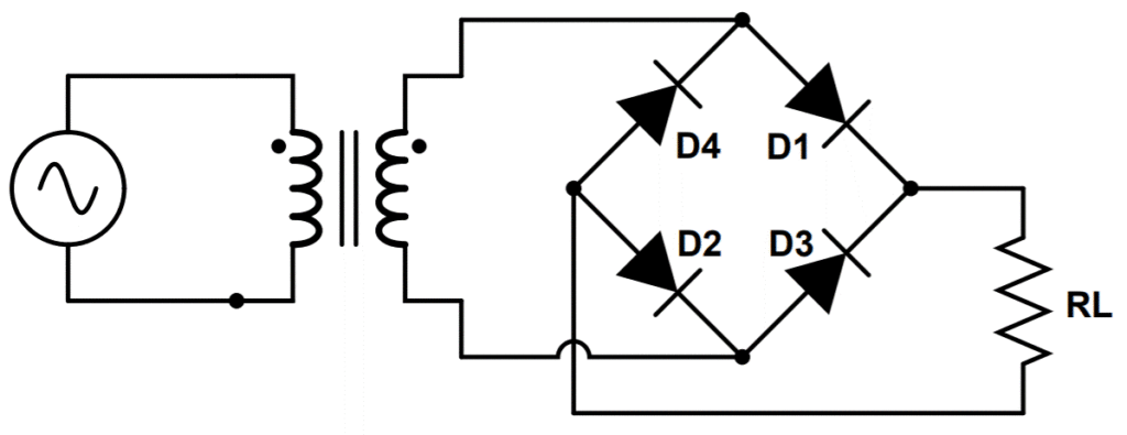
After rectification, the output still contains an AC component. To produce a steady DC voltage, a filter (such as a capacitor) is used to smooth out the ripples in the rectified voltage². A regulator can also be used to remove any remaining ripples and provide a constant output voltage².
Rectifier diodes are a vital component in power supplies where they are used to convert AC voltage to DC voltage¹. They are capable of conducting high electric current values and voltages up to a few kV¹.

Diodes can be used as protection circuits in several ways due to their ability to restrict electrical current to flow in only one direction⁴. Here are a few methods:
1. **Protection Diode**: Also known as a "fool's diode", it can be used to safeguard your device from reversed voltage and current¹. Diodes allow current to flow through them in one direction only, so they can block reversed voltages from moving current backwards through a system, sparing sensitive parts elsewhere in the device¹. The simplest installation installs the diode in series with the other components¹.

2. **Schottky Diode**: This diode offers a much smaller forward voltage drop than standard diodes (typically between 0.15V and 0.46V), which can improve voltage efficiency¹.
3. **Parallel Protection**: Another diode-based protection method is to wire a diode in parallel to your main circuit, causing it to block current when voltage is applied correctly¹. Once reversed, this diode provides an alternate path for electrons, largely bypassing the main circuit and protecting it from these effects¹.

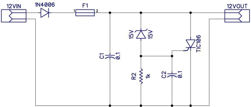
4. **Overvoltage Protection**: A “crowbar” circuit can protect your device from overvoltage². When the input voltage reaches a certain level, the Zener conducts, setting up a voltage across a resistor. When this reaches the trigger voltage of the SCR (less than 1V), the SCR fires, creating a short circuit across the input, which causes the fuse to blow².
5. **Overcurrent Protection**: If the voltage between the base and emitter of a transistor gets to 0.6V, the transistor starts to turn on. This then “robs” current from the base of another transistor, causing it to start shutting down².

Comments
Post a Comment